Introduction
I recently ordered an RGB2HDMI adapter made by Piotr Bugaj via the SellMyRetro website here. The device cost me 55 GBP + another 5 Euro postage. I was excited to test this alternative method of showing Amstrad content on modern monitors as I’ve been using the following method on my LCD for the last few years.
The hardware is based on a publicly available GitHub project called RGBtoHDMI which was originally designed for the BBC Micro but works on many different systems. The hardware runs on a Raspberry Pi Zero W v 1.1. You can get details about the RGBtoHDMI project here.
When the device arrived it came with an anti static bag, a receipt, no instructions and a DIN 6 cable to connect from the RGB2HDMI adapter to a CPC 464/6128 . There is also a CPC + cable available for purchase from Piotr but I did not get one.
The original for sale post on SellMyRetro says a 5v power supply is required, but basically any USB-A cable with a mini USB-A connector that is connected to 5v output will do.
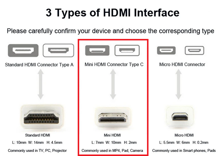
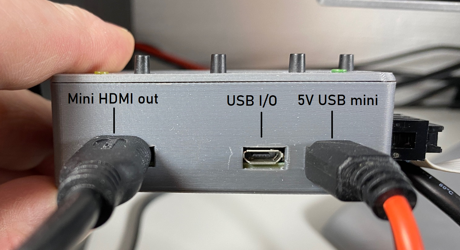
What it didn’t mention was that you’ll also need a mini-HDMI cable connector to connect up to your LCD or monitor. The mini-HDMI connector is shown in the red box below.
I ordered a mini-HDMI cable that had a DVI connector on the other end which I could connect to my old Dell LCD. I also sourced a USB-A to USB-A mini cable which I’ll use for powering the device by connecting it to a USB-A powered port.
So what’s in the 3D printed box ?
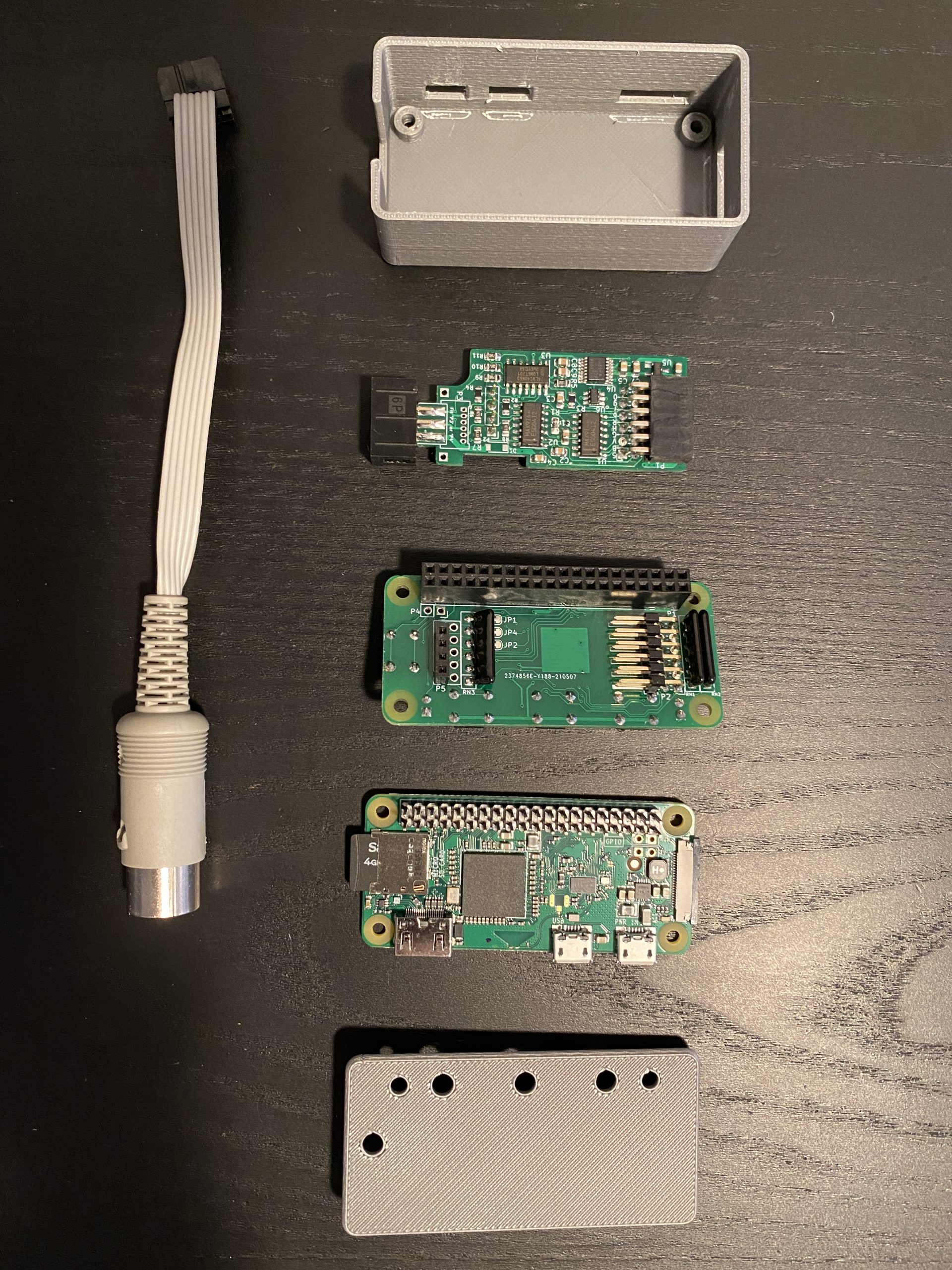
I carefully removed the device from it’s enclosure to get a close look at what it’s made of, you can see it disassembled here. At the bottom of the photo you see the Raspberry Pi Zero W v 1.1 and there are a further two mini boards that sit on top of it.
Both of the other boards belong to the RGBtoHD project, one is a Three/Four level analog RGB/YUV & composite monochrome interface for RGBtoHD, and the other is the RGBtoHD 12 Bit issue 4 board which contains the switches and leds as well as the Xilinx CPLD.
Strangely, none of the boards are branded with Piotr’s usual ZAXON brand.
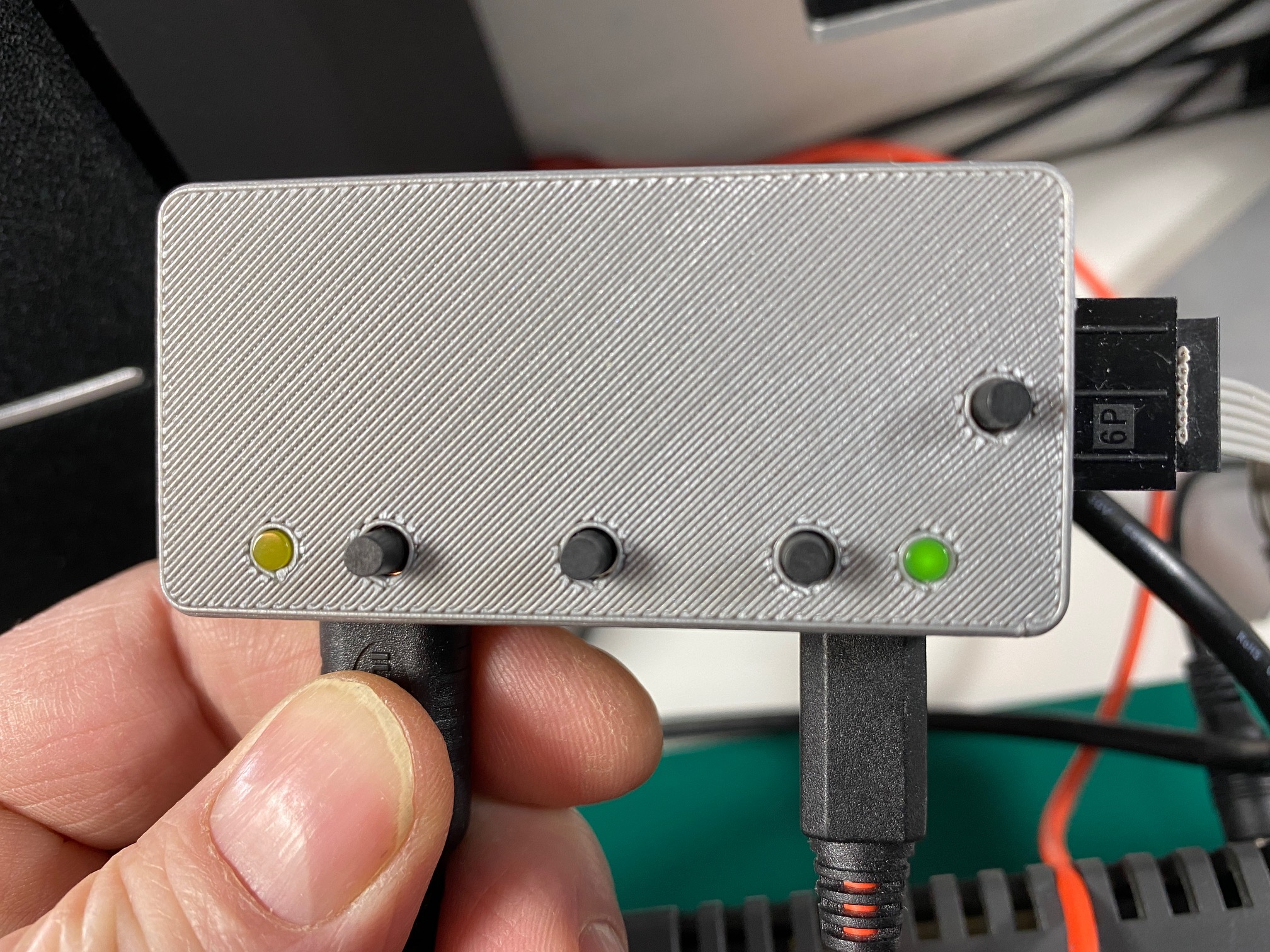
After connecting everything up and playing with the device, I determined that the three horizontal switches and LED’s on the device work like so. It would be useful if this information was shared with the device in printed format or better yet, 3D printed on the device.
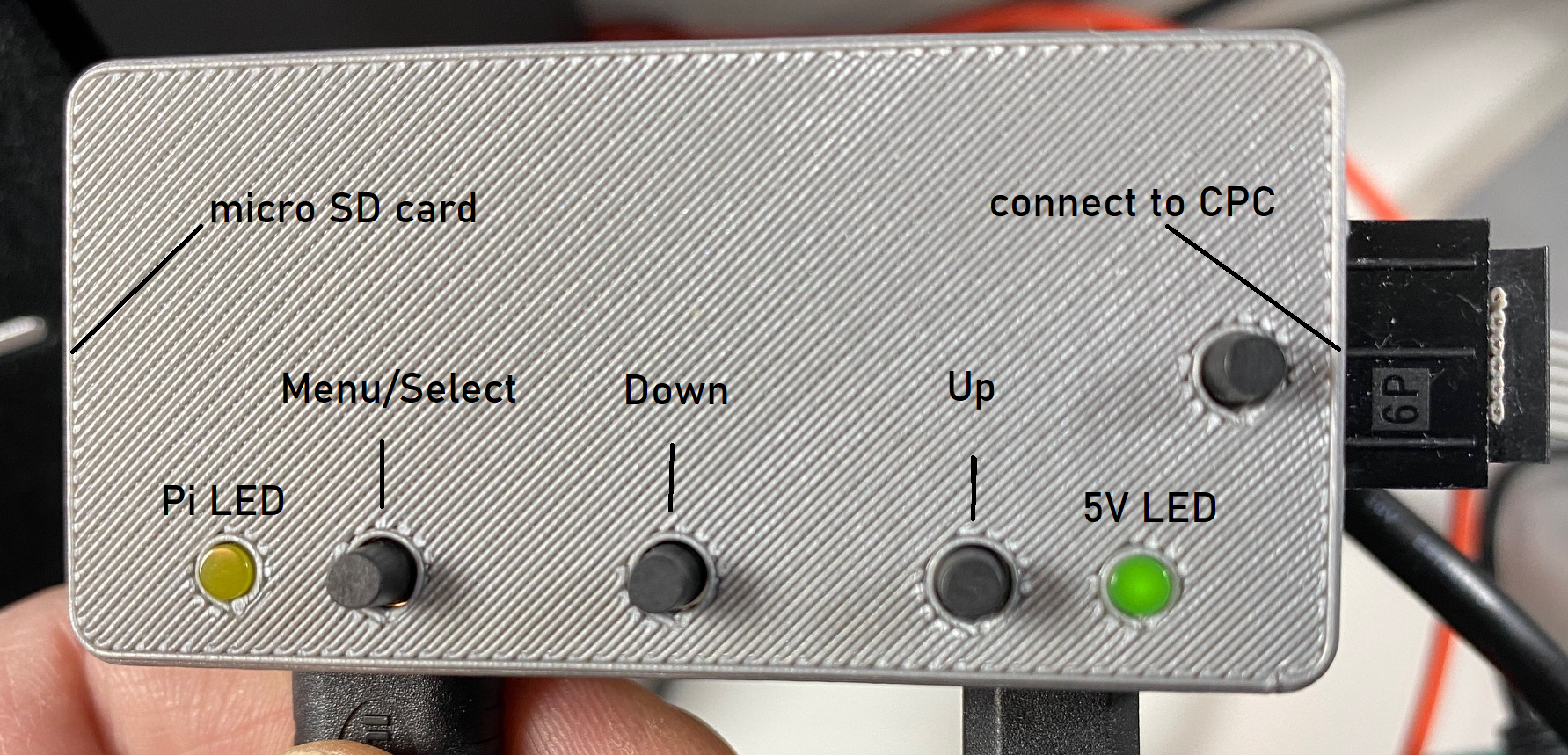
According to the wiki quick start guide the buttons do as follows:
SW1:
Short press = Call up menu
Long press = toggle scanlines (if available) on/off
SW2:
Short press = Screen capture (File is written to SD card)
Long press = Toggle NTSC artifact colours on/off
SW3:
Short press = Enable (if disabled) or refresh genlock
Long press = Calibrate sampling position
When the menu is on screen:
SW1: Select menu option or enter editing mode for the selected parameter
SW2: Cursor Down or increase selected parameter
SW3: Cursor Up of decrease selected parameter
Pressing SW2 and SW3 together will take a screen capture with the menu on screen
A fourth button SW4 can be used to reset the Pi but only if an additional 2 pin header is fitted on the Pi zero.
Connecting the device
To use the device, connect a 5v mini USB-A power cable to the mini USB-A port on the right side under the 5V LED, and connect your mini HDMI cable to the mini HDMI connector. You can see those cables are connected here along with some explanations of what the ports are.
 On the left side of the device, is the micro SD card slot where a 4GB card contains the files needed for the solution. On the right side there’s a 6 pin connection slot for a cable supplied with the device, that cable is either for connecting to a CPC or CPC+ model, depending on what you order.
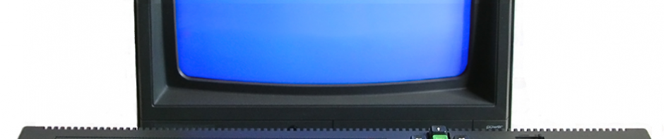
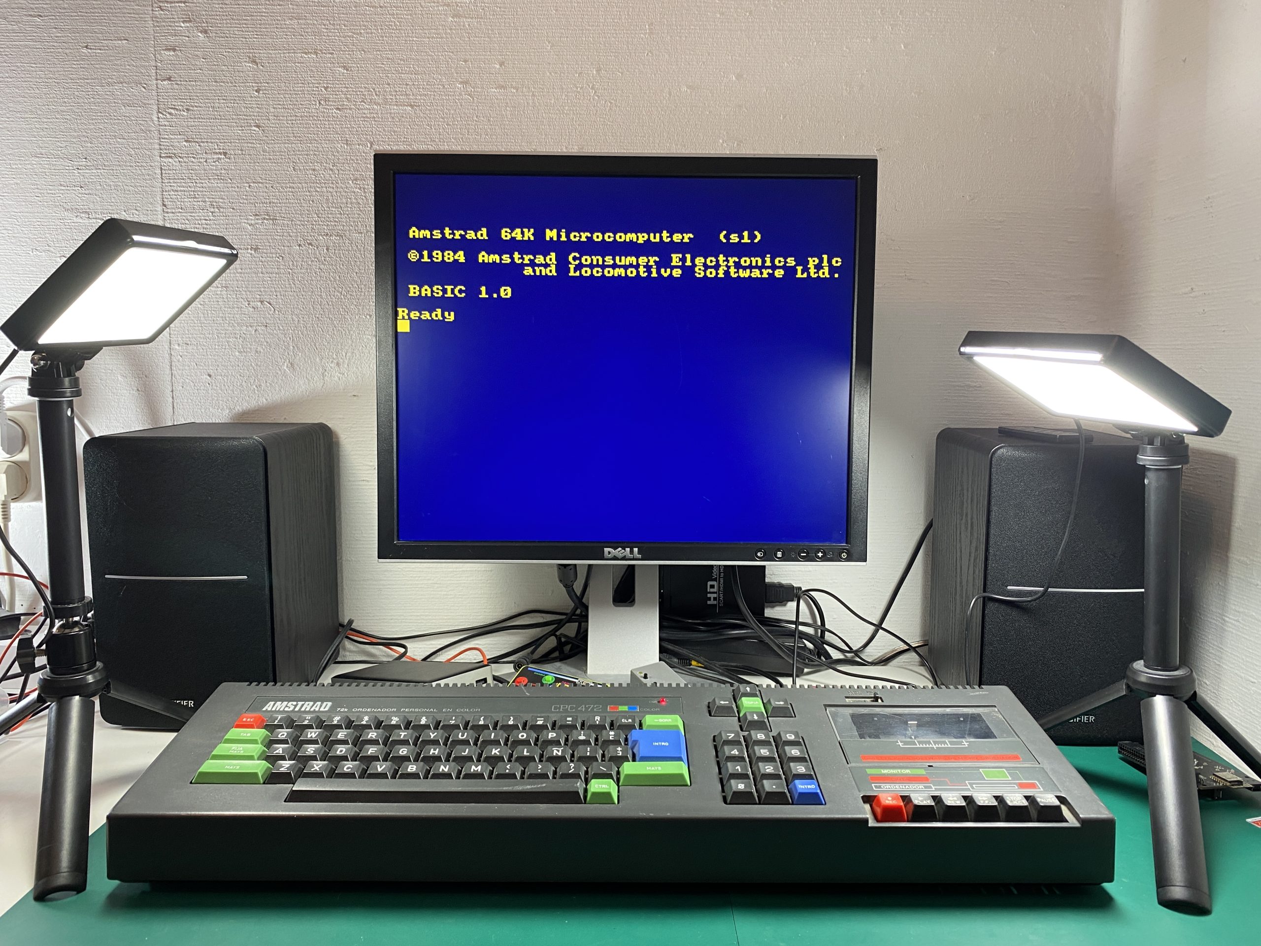
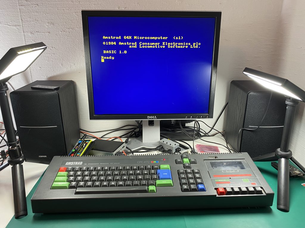
Once you have connected the device it’s time to turn everything on. I connected up an Amstrad CPC 472. I noticed that the borders normally evident on an Amstrad monitor were not present, in other words the text went right to the edge of the screen. You can see that in the photo below.
 After some digging around in the settings, I later found out in the configuration where to change that setting, more about that later.
The colours are bright and cheerful, there is little if no noise on the screen, it really looks great.
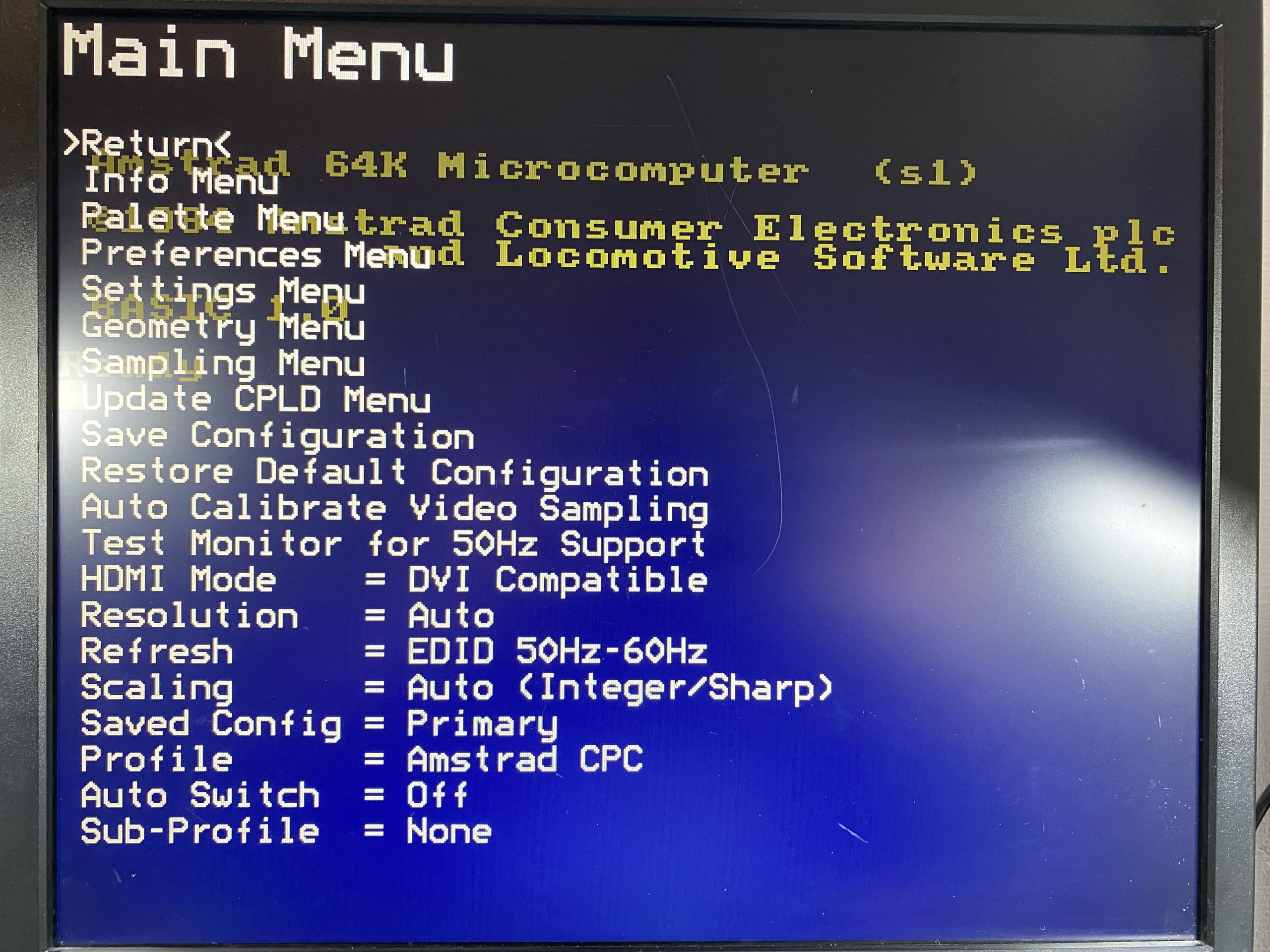
Using the On Screen Menu
The power of this device is in that it is flexible, and there are lots of settings that you can play with in the on screen menu (OSD). Pressing the first button brings up the menu, and you can then scroll through the settings or change them, it’s very easy to do so and intuitive.
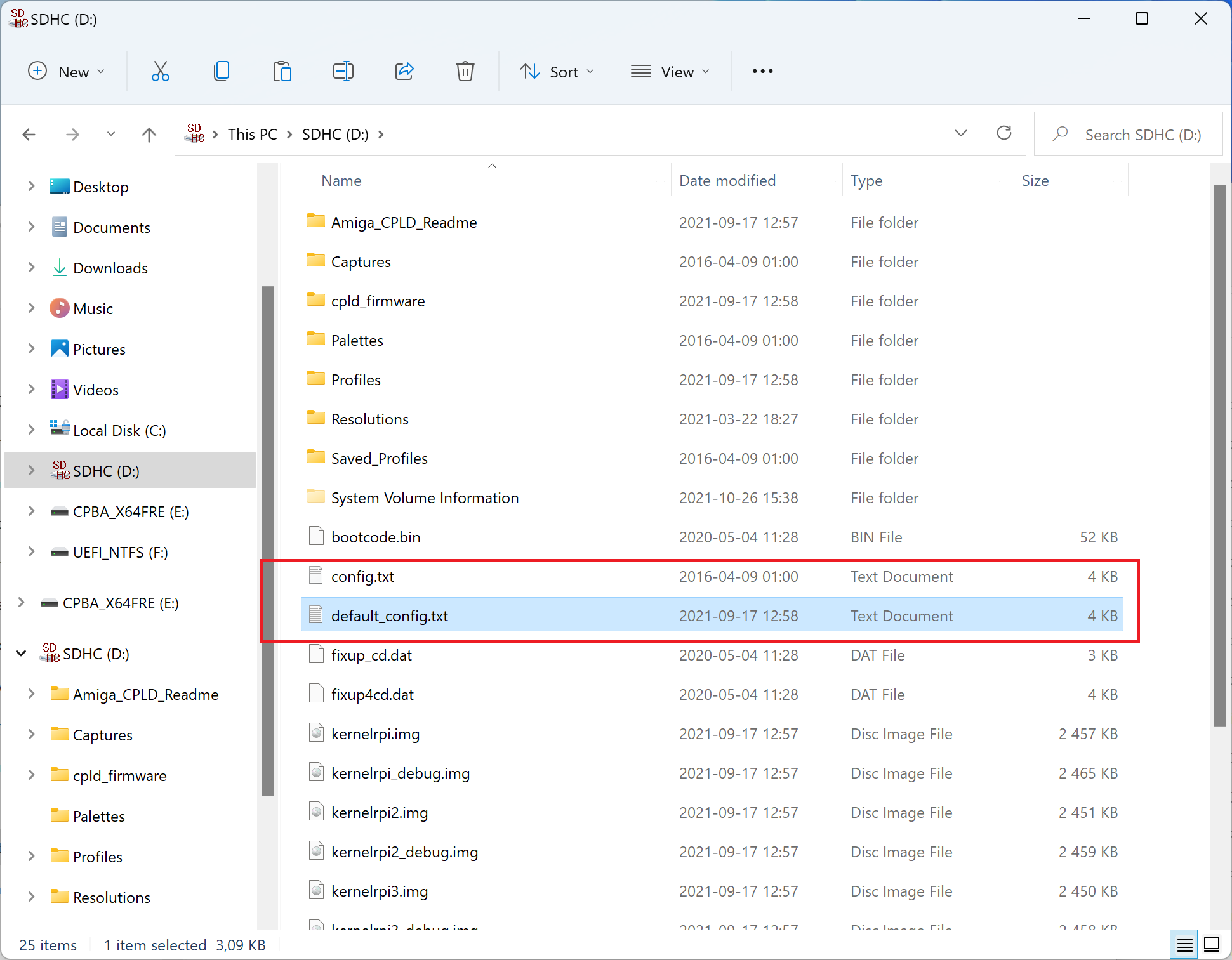
Note: be careful about what you change as you can screw it up, for example I played around with the resolution and after saving the changes and rebooting the Pi, I got no video. To solve that I had to eject the 4GB mini SD card, mount it on my PC and copy the contents of the default_config.txt to config.txt. You can see those files below.
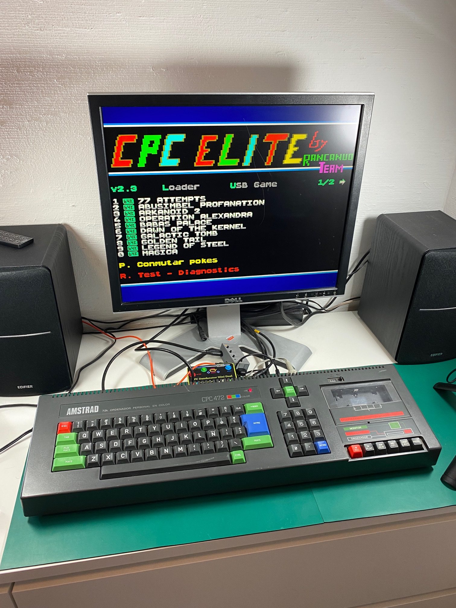
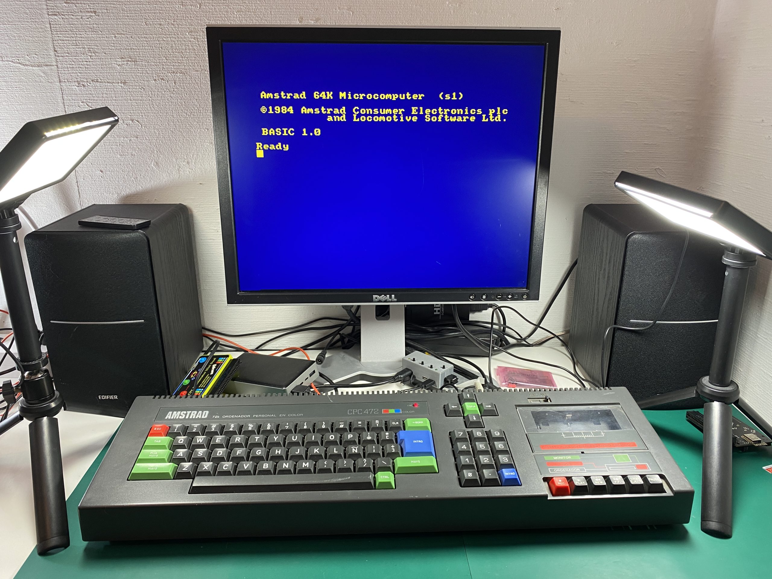
Remember the no-border I talked about before ? to change that simply bring up the OSD and navigate to Scaling. Mine was set to Auto (Integer/Sharp).
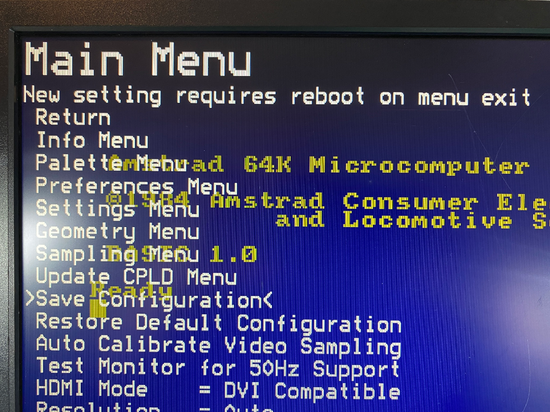
After pressing the menu button and changing that setting to Interpolate Full/Soft I got the Amstrad border look I wanted.
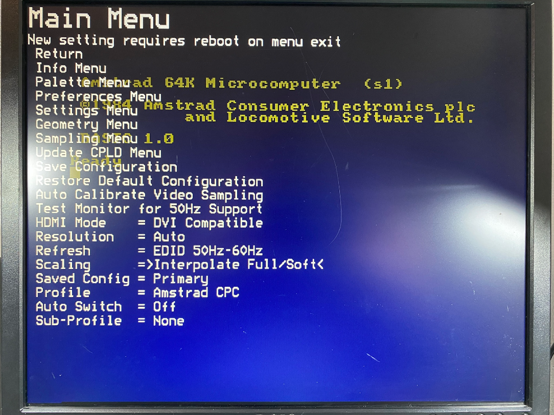 Don’t forget to Save your configuration by selecting Save Configuration. Followed by Return, it’ll inform you that a reboot is needed.
 After changing the setting, it looks like this, which is more accurate in terms of an Amstrad display.
 Saving screen captures from the CPC
The RGB2HDMI comes with another great feature and that is the ability to take screen captures from the CPC. Below are some screen captures I took, it’s so easy to do and really show’s the power of your CPC.
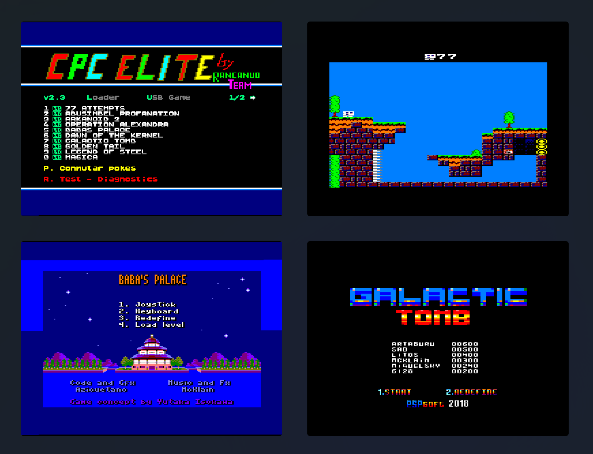 It’s simple to activate, just press and hold the middle button in for a few seconds when not in the OSD. Once done, you’ll briefly see a message across the screen telling you where it’s saving the screen capture and it’s file name. Check out these sample screen captures, amazing quality !
Conclusion
The RGB2HDMI device is very nice indeed, it’s tiny, and it’s small size hides it’s power. It’s built on well established hardware using a publicly available GitHub project so development will continue for a long time I’m sure. It’s encased in a nicely 3D printed case and the price is OK, considering what you get. Well done Piotr on making this available for the Amstrad CPC and CPC+ computers. Hopefully he’ll read this and include some of my thoughts in the next version.
well that’s my first look at the RGB2HDMI, what do you think of it ?
cheers
niall
Cool LED Lamps! Where did you get them?
these were the lamps I purchased, they are nice ! https://www.amazon.com/gp/product/B07YFY7H7J/
Thanks for the review – I wish it was possible to take a series of snapshots with that, or even capture short “video sequence” (maybe as a series of GIF images). That would be a killer feature and would convince me to buy one of these. Else I am totally happy with the picture quality and responsiveness offered by the Scart->HDMI converter that I am using since 5 years. But it seems to be a neat piece of kit. Now if that would also work with DIFFERENT retro machines, not only the CPC, that would be another killer feature… Cheers, Michael
it does work with other retro computers but you’d have to make up the connector cable yourself, i don’t think it would be too hard !
That’s amazing, it’s a must have, I actually messaged Ben Versteeg in Holland about this about 6 weeks ago saying your fantastic ZXHD Interface is readily available, are you able to make a similar Interface for the Amstrad CPC6128, his answer was quite possibly yes. So this may be the perfect solution to getting Crystal Clear Resolution. Great Work!!
Could you test it with Ghost n Goblins? It would be interesting to know if the device can handle hardware scrolling via CRTC register R3
i’ll try today !
do you have a link to a download of the game ? is there any specific part in the game you want me to focus on ?
The game can be downloaded here: https://www.cpc-power.com/index.php?page=detail&num=974
It would be interesting to know if RGB2HDMI or the other HDMI converter you have can handle the hardware scrolling from this game. You will notice during the gameplay whether the scrolling is clean or the display goes crazy for a short time because the converters lose synchronization before the image is displayed stably again.
ok i’ve tested it and uploaded a video to my channel, please check it out https://youtu.be/ZKrF3qWwUXM
Thank you, I was hoping for this result. You would have noticed if the device had had problems. The graphics during scrolling would then be complete garbage.
I have got all the components but it is unclear to me which firmware is needed for the CPC profile.
Could you check yours on the Info menu and tell me which CPLD type and firmware it is using , please ?
Thanks
Erik/LaSTiC
hi Erik,
i just checked and mine is as follows:
CPLD: 6 – 12_BIT_RGB_Analog v9.4
is that enough info for you or do you need more ?
Perfect, that was exactly what I needed.
Thanks , much appreciated.