Introduction
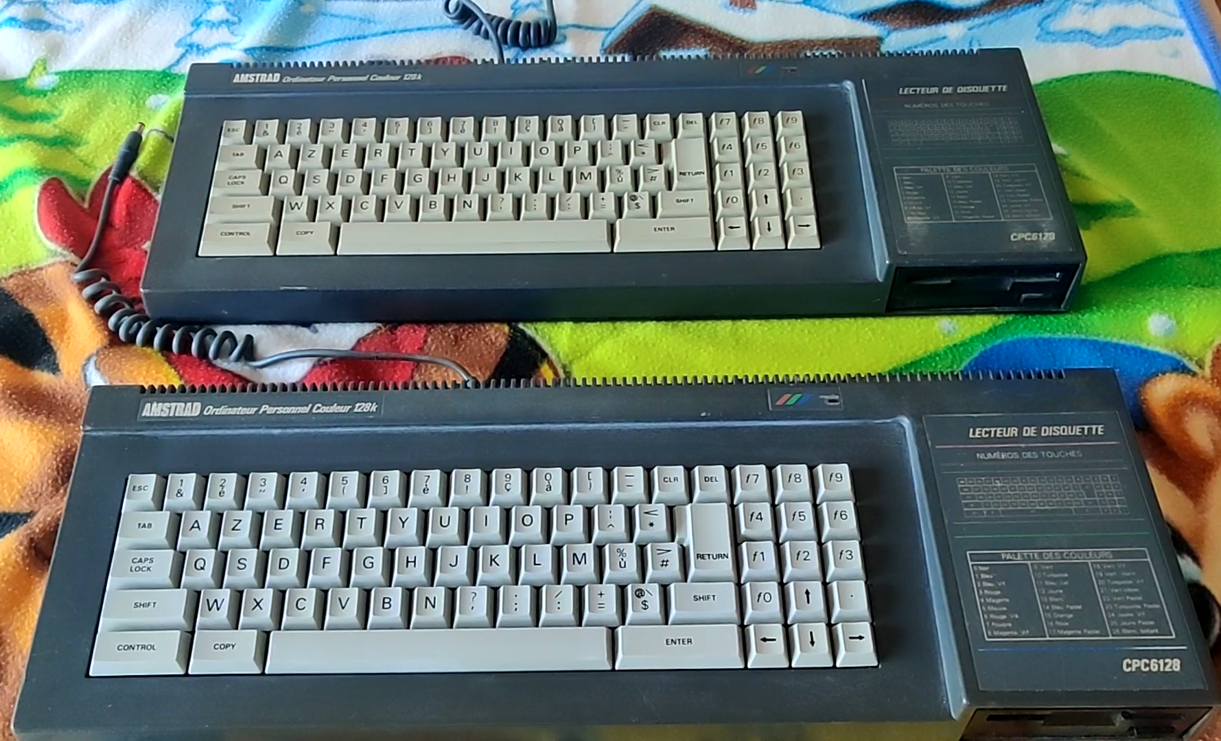
This is part 10 of a blog series I’m doing to catalog and revitalize one of the programs I wrote way back in 1988 on the Amstrad CPC 6128, which I called Disced. Back then when I had to learn something I did it by reading magazines or books and lots of trial and error.
Below are a list of previous blog posts on this subject.
- Disassembling my old code part 1 – Getting started with WinAPE
- Disassembling my old code part 2 – Setting screen mode & Soft 968
- Disassembling my old code part 3 – Text operations
- Disassembling my old code part 4 – Set cursor position & disc cache
- Disassembling my old code part 5 – Get Shift key and set translate
- Disassembling my old code part 6 – Processing disc activities
- Disassembling my old code part 7 – Drawing rectangles
- Disassembling my old code part 8 – Processing HEX in the left pane
- Disassembling my old code part 9 – Assembling the code
- Disassembling my old code part 10 – Code review <—- you are here
Well it’s been a long time since my last post on this subject and I apologize for that. Life, work, family and other things have taken priority but I’m always thinking about this, believe me. I do love my Amstrad beginnings so I’m always going to return to this when I can and right now I’m on my summer vacation so let’s see what we can achieve with this now!
Virtualizing WinAPE using Hyper-V
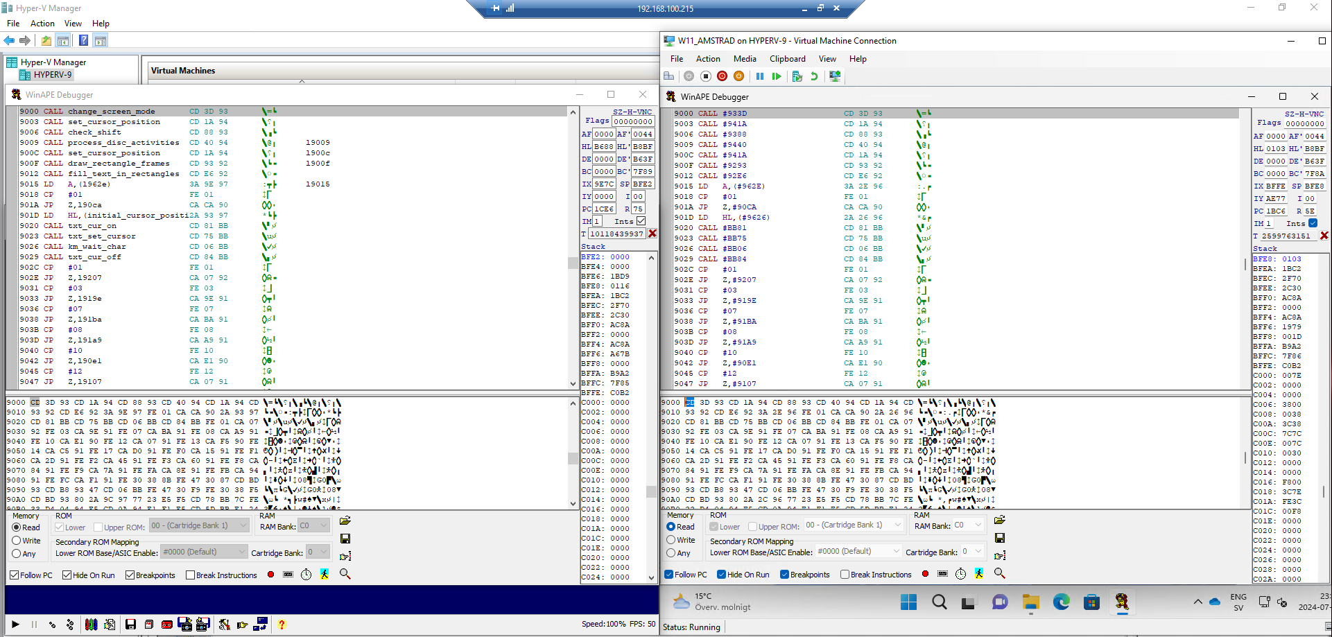
Side note, there’s one minor change since my last post, I’ve now created a dedicated Hyper-V virtual machine to simplify things and run another instance of WinAPE and use that to side-by-side compare the assembled code with the released version of DISCED code from 1988, this will speed up my code review (I hope).
For anyone wanting to do something similar, simply create a new Generation 2 virtual machine in hyper v and install Windows 11 22H2 or later, and then install the DirectPlay Windows Feature before moving forward.
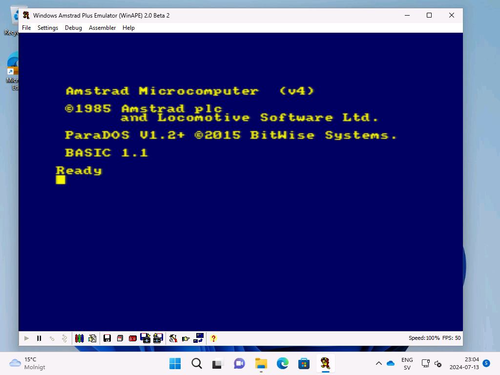
Launching WinAPE on the VM
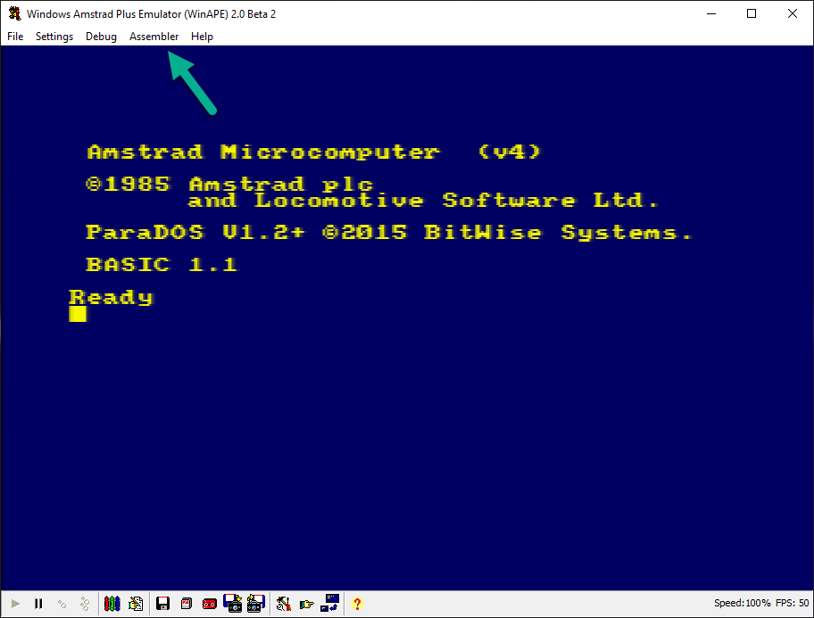
Once installed you’ll be able to launch WinAPE.
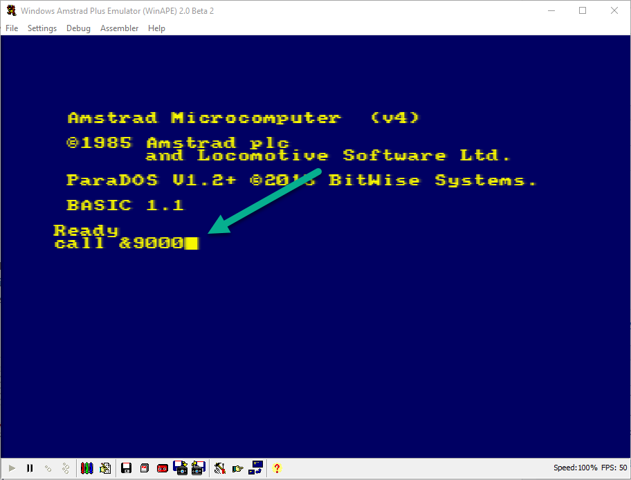
and get back to where we were with this blog series. To do that I ran disced from the mounted DSK file (drive A:)
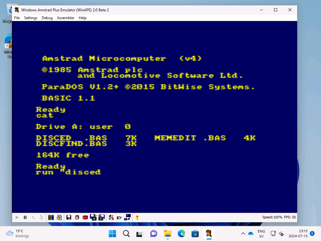
and after it launched DISCED
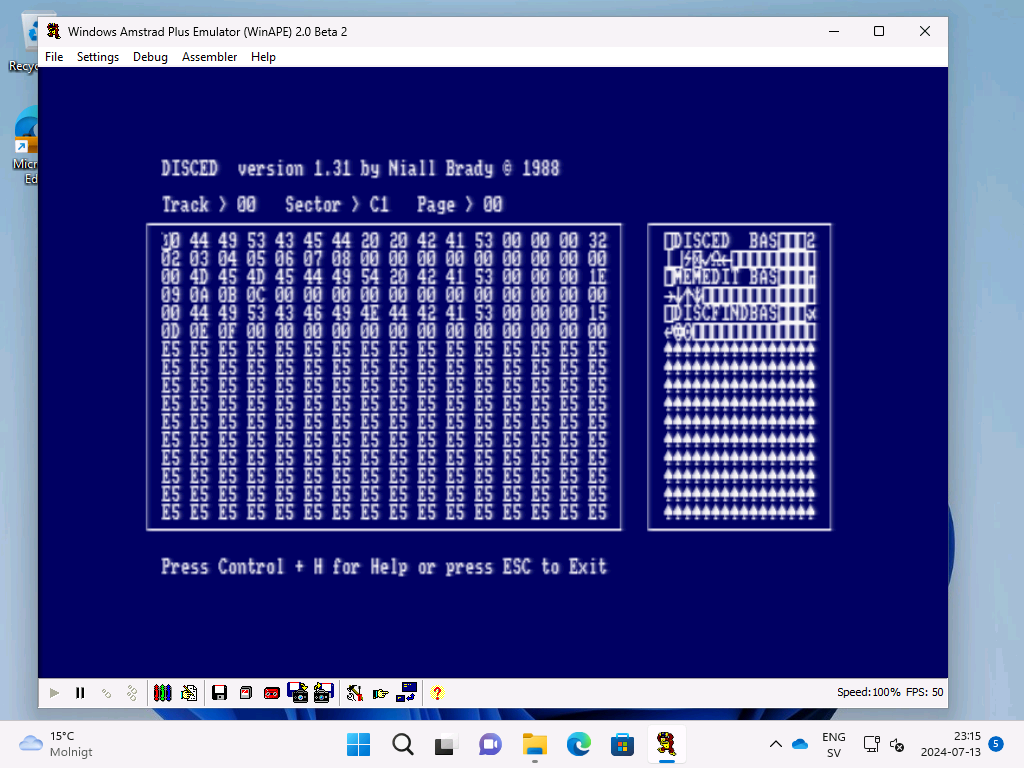
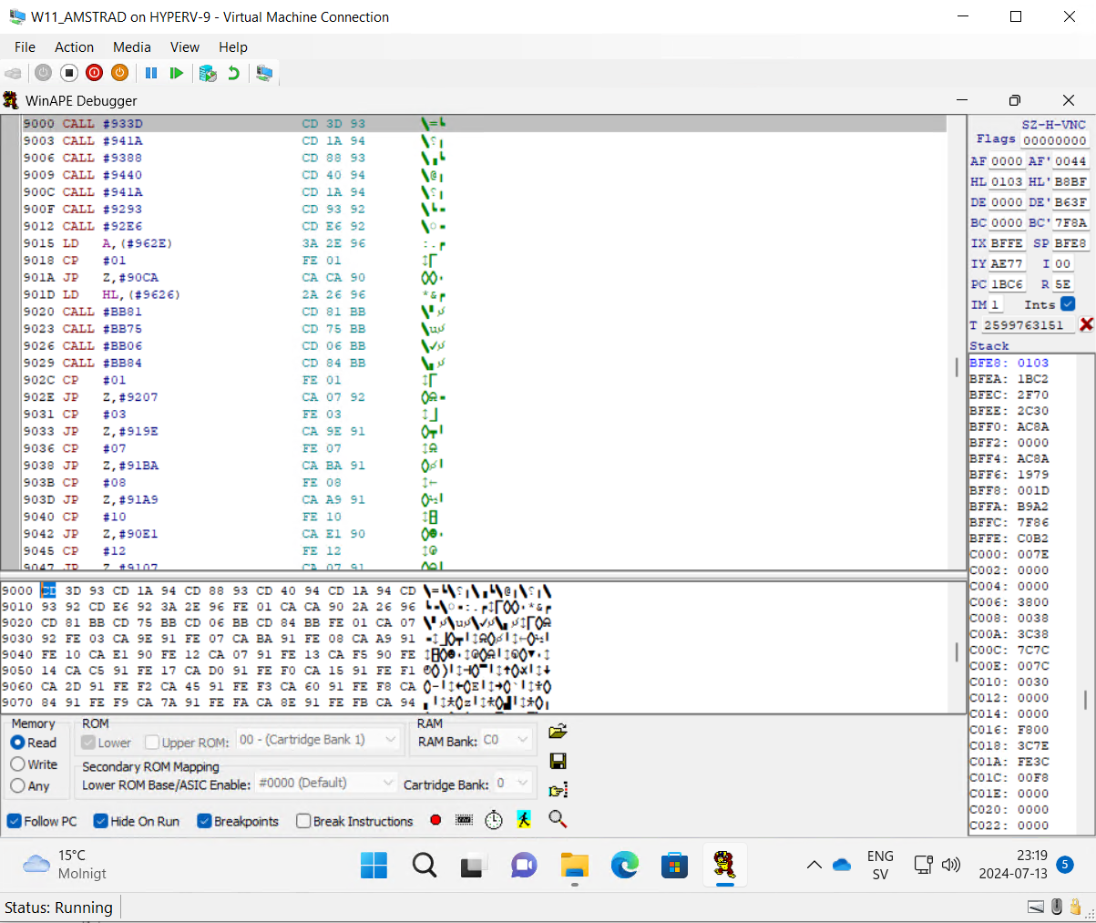
I quit Disced by pressing ESC and brought up WinAPE’s disassembler (F7), this gave me exactly what I need to compare the original disassembled code from 1988 to today’s changes.
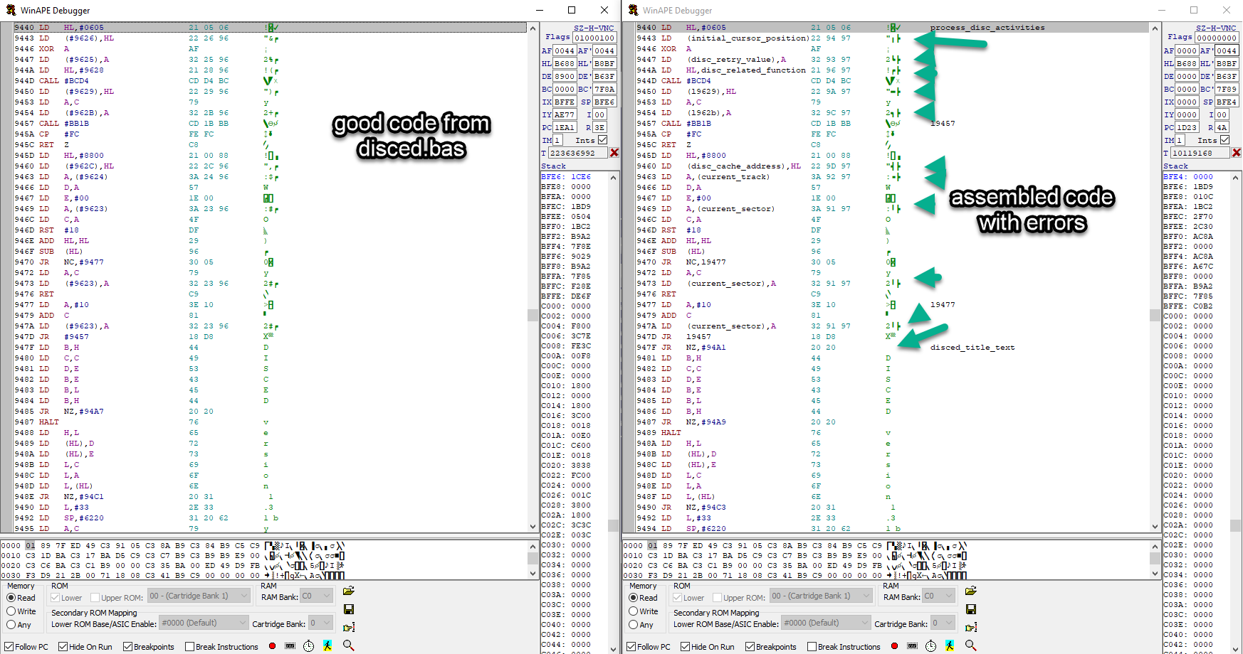
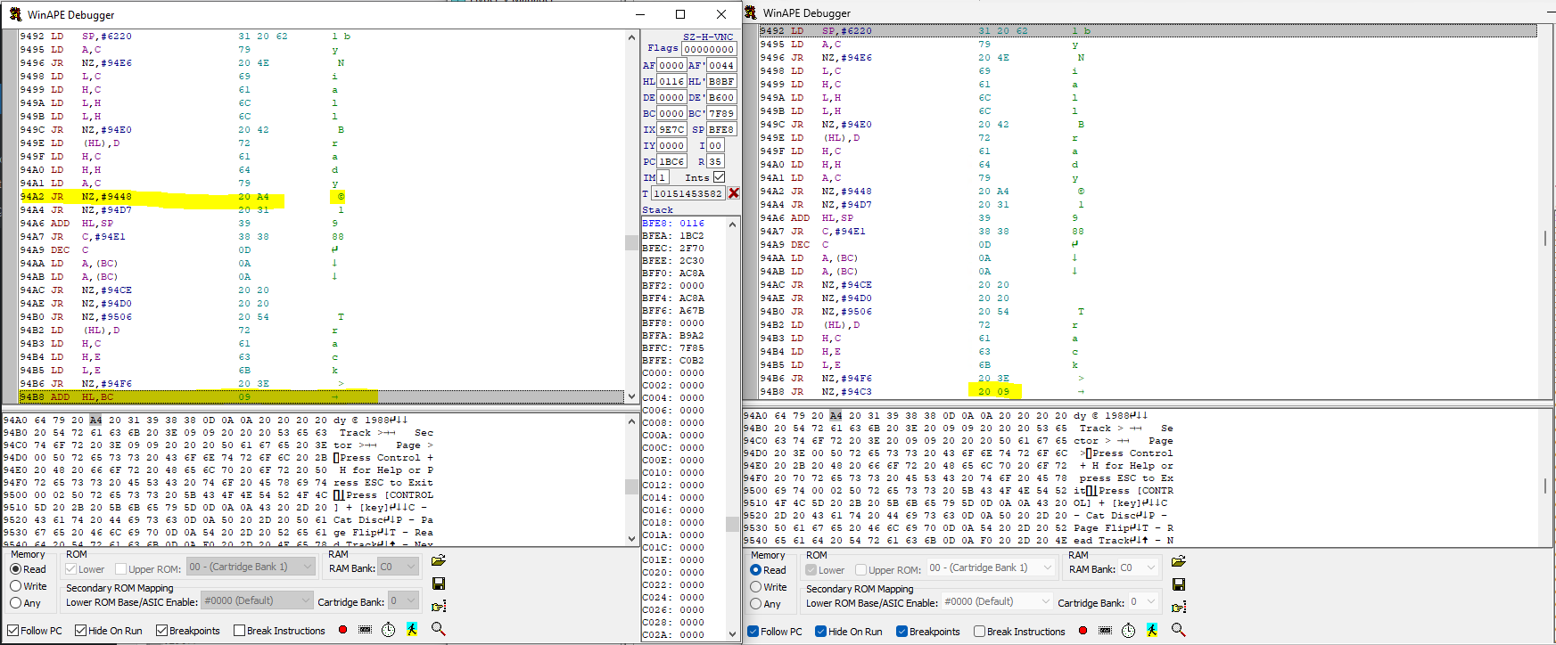
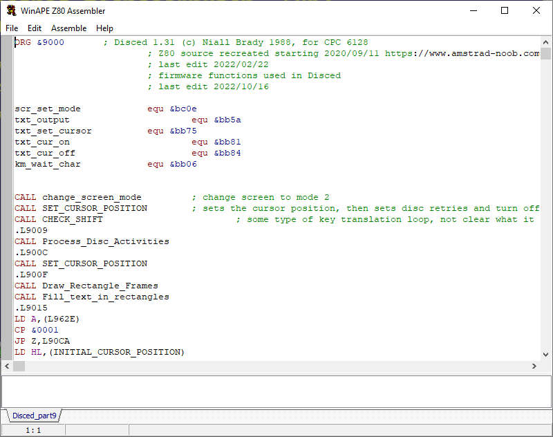
Below is a screenshot of the original code (starting at address &9000 hex) running in WinAPE on the virtual machine in Hyper V. I’ve previously explained how to do this disassembling in WinAPE in part 1 here.
Comparing the code
OK now that is out of the way, let’s compare the current code with the original.
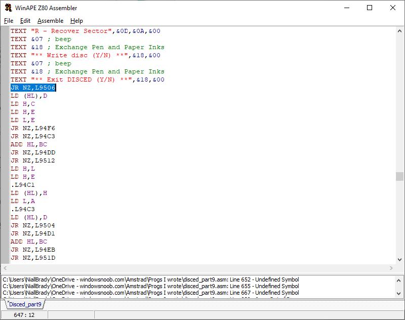
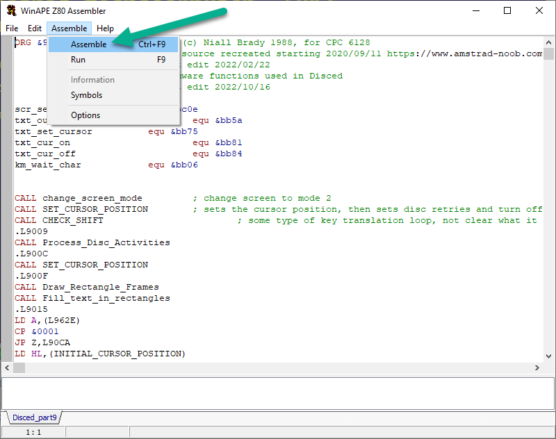
On my computer hosting WinAPE (not the VM, just the normal computer) I assembled the code as described in part 9. I know that this code crashes as soon as I try to run it so obviously something in the source code is off as I already found out in part 9 of this series.
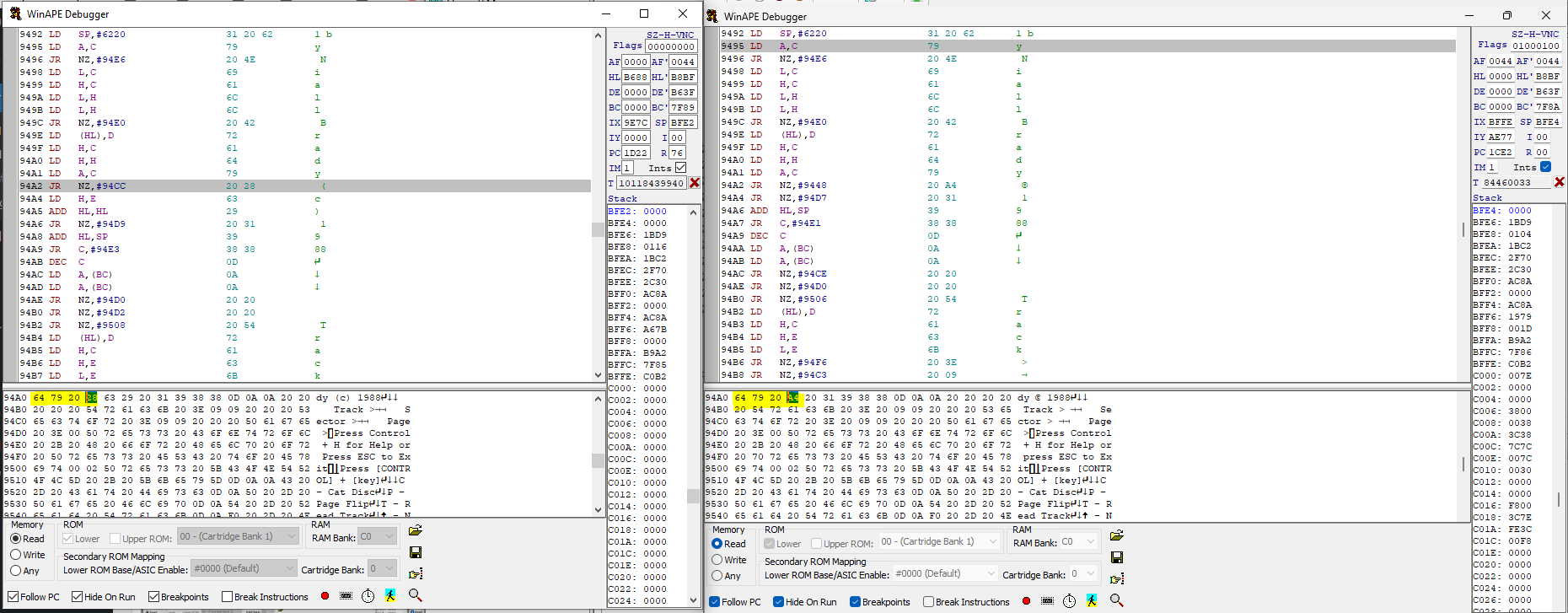
Once done, I can compare the original code (running on the new VM) to the newly assembled code (running on WinAPE on my local PC). In the screenshot below, that’s exactly what I’m doing, WinAPE on the local pc on the left, same screen from the VM on the right.
Using this method I used page down in the assembled code (on the left screen) and did the same on the code from 1988 until I found changes that looked wrong. The first obvious problem was the (c) symbol (hex A4) which I needed to resolve.
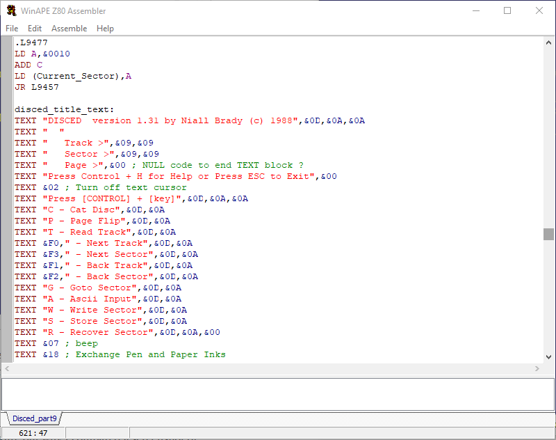
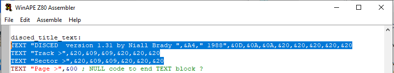
To fix it, I opened the assembler again, and found the line in question. This is before.
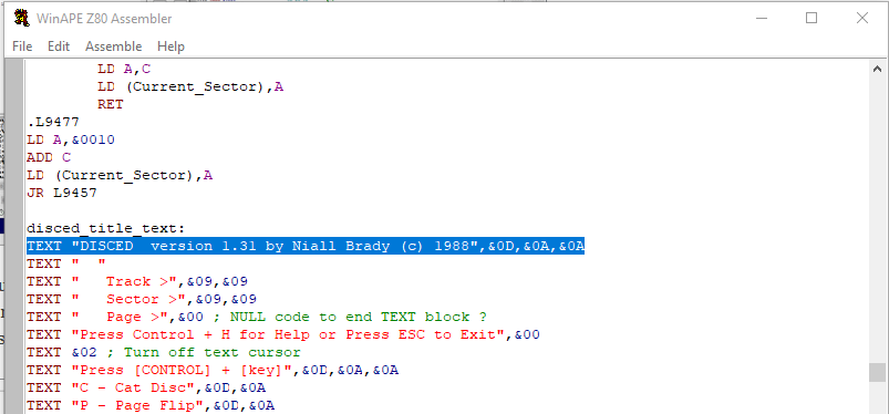
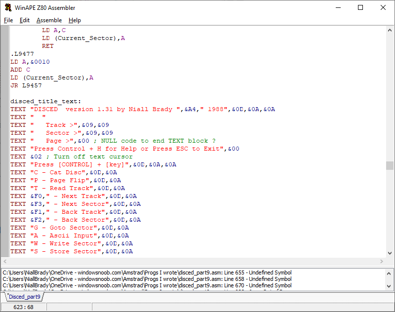
and this is my edit, I’ve removed (c) and replaced it with the copyright character in HEX
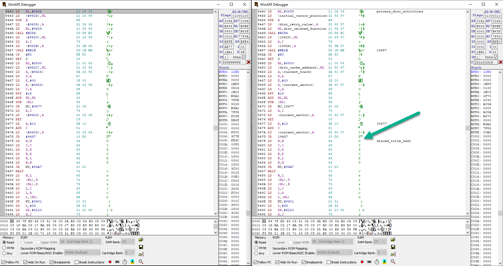
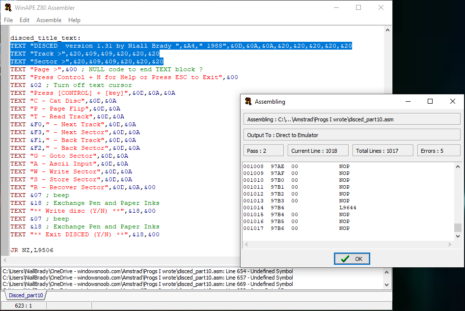
After making that change and reassembling the code, then disassembling it I could see it fixed that problem, but another one was revealed (a missing space).
So I modified the missing space and made some other changes to the source code as you can see here.
I then saved the changes, and re-assembled the code.
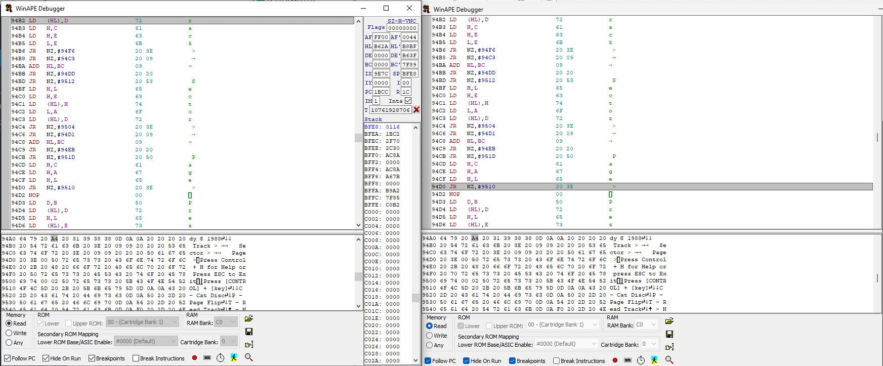
Finally, I verified (by disassembling) that the changes worked, and by worked I mean that the right code appears in the left disassembled code box.
And it did ! Success.
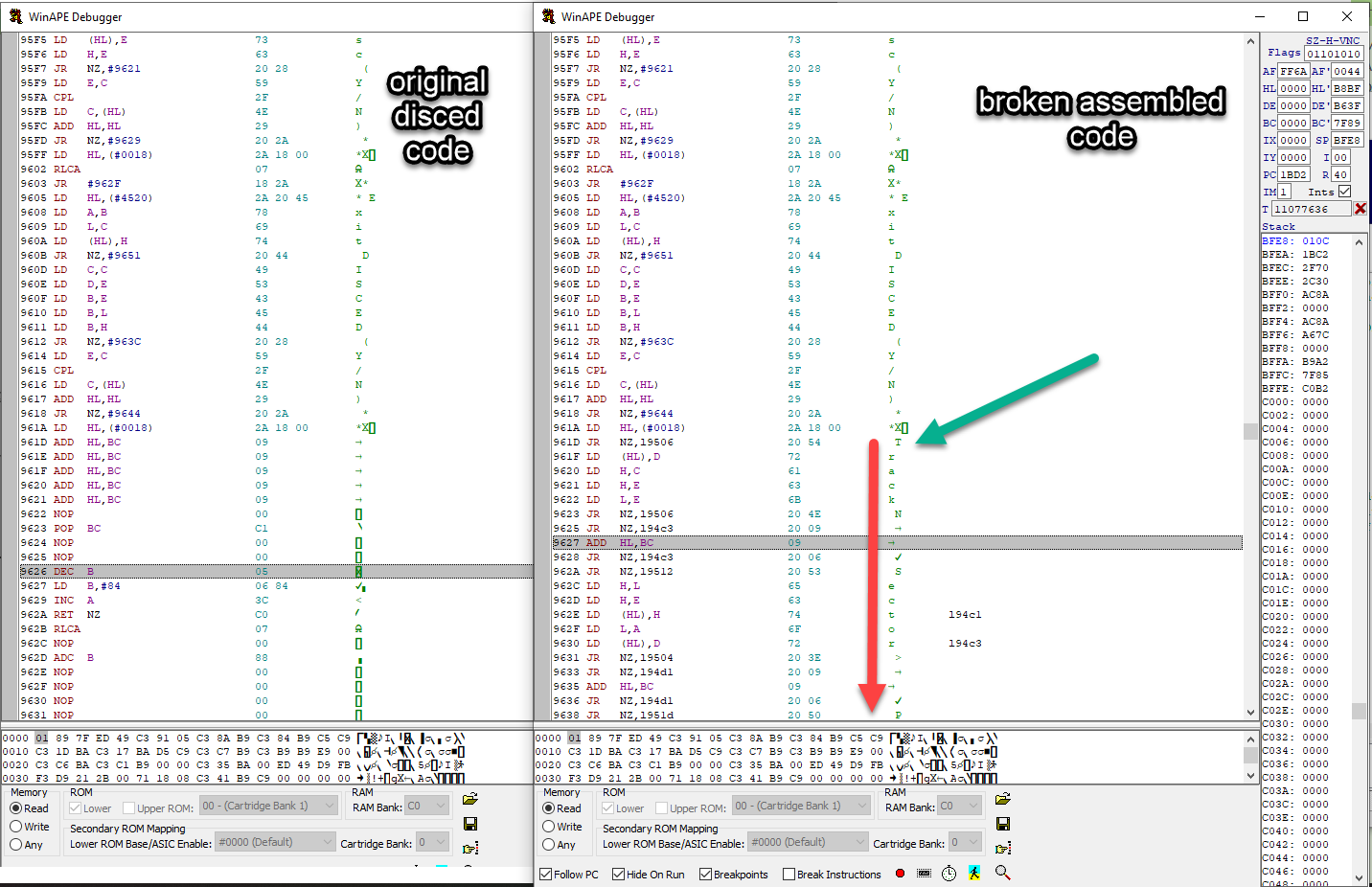
At this point, even though it’s tedious I’ve found a way that works for me. Please remember that I don’t work with Z80 machine code so all of this is a re-learning process for me and I have to do it when time permits.
The method that works for me currently involves stepping through the code using two instances of WinAPE one running from the ‘new’ source code and one running from the original code. I then compare the newly assembled code with the old original code, fix the differences by editing the source code, save, then reassemble, disassemble new changes and continue.
Now I just have to repeat this method until the code ends. The goal here for this part of the blog series is to get the source code working 100% so that I can release it to GitHub and you or me can make changes to it.
I’ll continue with this code review (and hopefully code release) in the next part, coming soon (I promise).
but for now, here’s where I am with this project, the code used in this part (and the other parts) can be found on Github here.
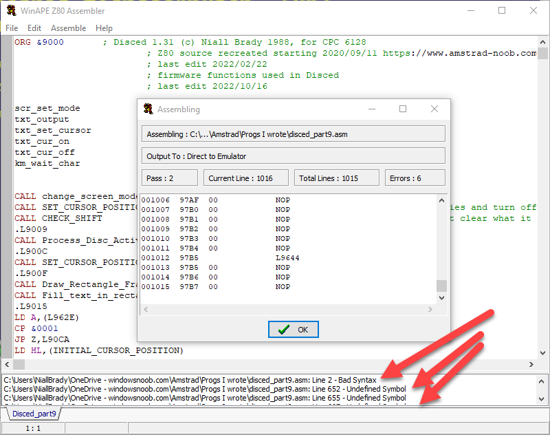
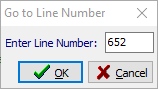
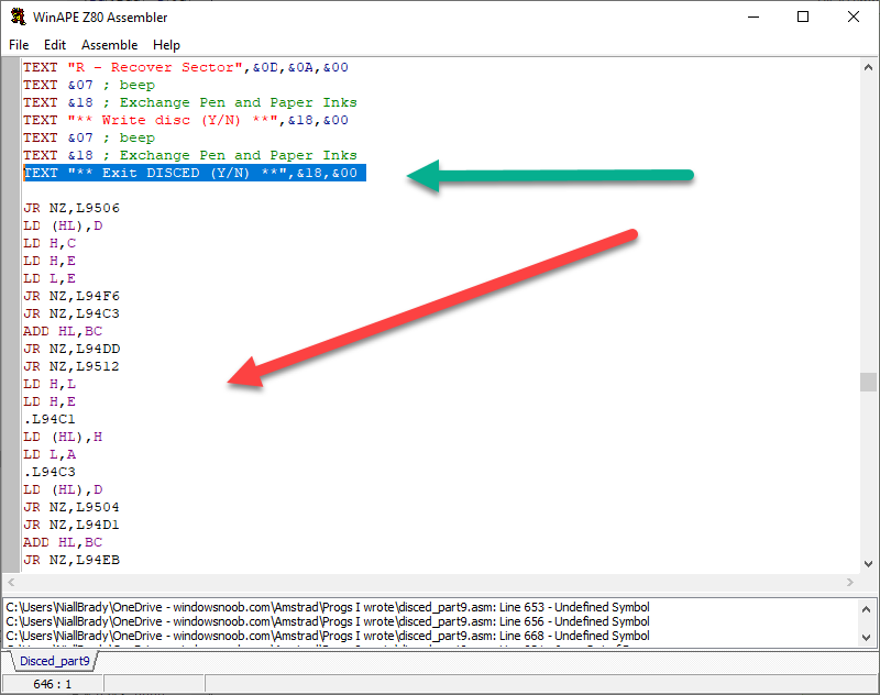
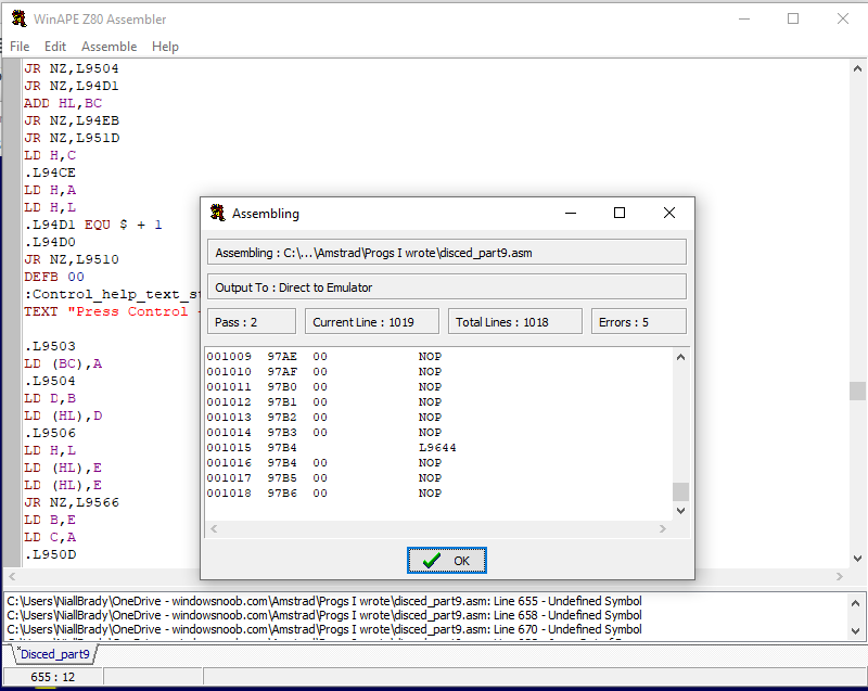
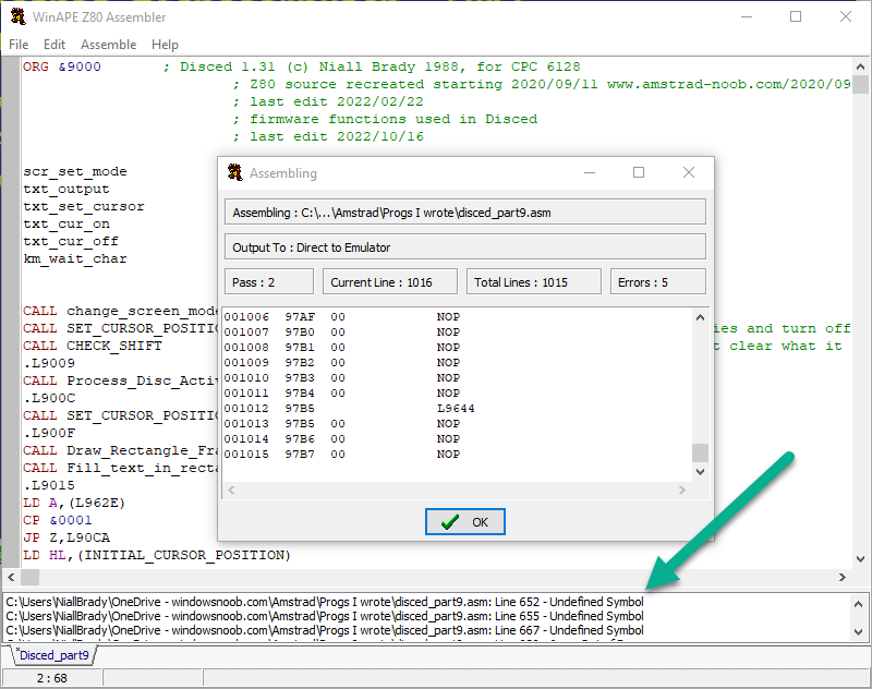 Next we need to find out what is wrong with Line 652 – Undefined Symbol. To speed that up, let’s use CTRL+G to go to the line number 652.